Configuring a DLINK switch(with screenshots)
Creating
VLANS in D-LINK switch using Web interface
For this guide we
are going to use two VLANS. They are;
-
Management VLAN
VID = 99
VLAN name = Mgtvlan
-
Floor VLAN
VID = 140
VLAN name = Floor400
IP range = 192.168.140.0/24
-
Public VLAN
VID = 50
VLAN name = PublicVL
Reset the switch.
Then change the IP address of the PC of the Ethernet adapter to an IP
of range 10.90.90.0/24. (For this example we used 10.90.90.2)
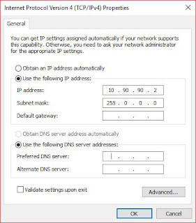


Connect the
Ethernet cable to the port 1 of the switch. Open any web browser and
type 10.90.90.90 and enter.
The default login
password is admin. Login using the password. Once logged in,
there will be a window as below.

Mark the Ignore
the wizard next time check box and click exit.

In the following
window go to the System tab in the left panel of the window.
In System, go to System settings and configure
the System Information. For this example, we use the
followings.
System name =
Floor400
System
location = Floor400
(Leave the Login
timeout value as it is)
Apply the
changes.
Then configure
the IP Information. For this example, we use the followings.
IP address =
192.168.99.141
Netmask = 24
(255.255.255.0)
Gateway =
192.168.99.254
(Leave the DHCP
configurations as it is) Apply changes.

Once the System
IP configurations are changed, the connection to the switch through
web browser will be lost. Then change the IP configuration of the PC
Ethernet adapter to an IP of the Management VLAN.
For this example,
we use the followings.

Now the switch
can be accessed by the IP address given in the System settings
configuration. (In this example 192.168.99.141) Log in again using
the password admin.
Adding
new VLANS
Go to the VLAN
tab in the left panel of the window and go to 802.1 Q VLAN tab.
Then click the Add button.
Adding
Management VLAN
Give the VLAN ID
(VID) and VLAN name. (For this example, we used the details mentioned
at the beginning of the document). Select tagged for
the port 24 in this VLAN. Select untagged
for port 1 and select Not a member for
all other ports. (2-23) and apply changes.

Adding
Floor400 VLAN
Give the VLAN ID
you want and a name to the VLAN. (For this example, we used the
details mentioned at the beginning of the document) Select tagged
for port 24 and select untagged for the
ports form 3-23 and apply changes.

Go to default
VLAN and select Not a member for all the ports except
port 1 and apply changes.

Go to the 802.1
Q Management VLAN and change the VID to the VID of the Management
VLAN. ((For this example Management VID is 99) and apply changes.

Then connection
to the switch from the web browser will be lost. Change the cable
from previous port to the port untagged in Management VLAN (In the
example, from port 1 to 2) and log in to the switch.. Go to the VLAN
settings and go to the default VLAN. Select port 1 to
Not a member. Then go to the Floor VLAN (In this
example, Floor400 VLAN) and select port 1 to untagged
and apply changes.
Adding
PublicVL
Add a new VLAN
and give the VID and VLAN name. (In this example we used the details
of the PublicVL mentioned at the beginning of the guide).
Select port
24 to tagged and apply changes.
Removing
the port assigned for the Management VLAN
Change the
current IP address of the PC to an IP of the Floor VLAN range. (For
example, if the Floor VLAN is in the range 192.168.140.0/24 give the
IP as 192.168.140.2) Connect the Ethernet cable to port 3 and log in
to the switch using the browser (In this example, we use
192.168.99.141). Go to the VLAN tab and go to Management VLAN
(99). Select port 2 to Not a member and
apply changes. Go to the Floor VLAN (In this example VID = 140) and
select port 2 to untagged and apply
changes.
In
the left upper corner click the Save button and Save configurations.


NOTE
If
there are more than one switch, then select both ports 23 and 24 to
tagged except one switch.

Comments
Post a Comment